Mengatasi Error Code pada Fotocopy Canon
Panduan pengguna Cara Mengatasi Error Code pada Fotocopy Canon Anda yang Rusak, Error Code dan masalah umum lainnya seperti kertas macet serta pembersihan dan perawatan mesin fotocopy.
- Canon IRA 6055
- Canon IRA 6065
- Canon IRA 6075
- Canon IRA 6255
- Canon IRA 6265
- Canon IRA 6275
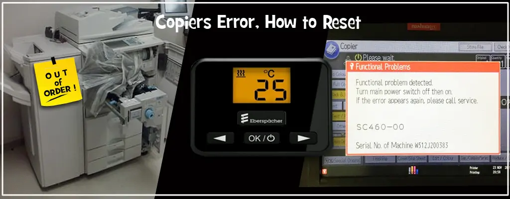
Fixing Assembly low temperature error
Temperature of the Fixing Main Thermistor (THM1) does not reach 70 degC although 20 seconds have passed after starting the Fixing Roller temperature control.
Memperbaiki :
- Check the connection of the Fixing Assembly. (Connection error of the Drawer, connector disconnection, open circuit) -> Replace the Heater Assembly.
- Check the connection between the Main Driver PCB (PCB2) and the Fixing Power Supply PCB (PCB10) (connector disconnection, open circuit, the caught cable).
- Replace the Fixing Power Supply PCB (PCB10). 4. Replace the Main Driver PCB (PCB2). 5. Replace the DC Controller PCB (PCB1).
Description : Fixing Assembly high temperature error (hardware detection)
Abnormal temperature difference among the Thermistors was detected.
Memperbaiki :
- Check if the cable of the Thermistor is caught or is open circuit. -> Replace the Thermistors. -> Replace the Fixing Upper Unit.
- Replace the Main Driver PCB (PCB2).
- Replace the DC Controller PCB (PCB1).
- Check if the Fixing Shutter operates. -> Replace the Fixing Assembly.
Description : ETB disengagement error, Disengagement of the ETB is not completed within the specified period of time.
Perbaikan :
- Check the connection of the ETB Disengage Sensor (PS56). Sensor side: J2101, J3270, PCB side: J343 (Duplex Driver PCB (PCB4))
- Check the connection of the Duplex Feed Left Motor (M19). Motor side: J2107, J3044 (relay), PCB side: J330 (Duplex Driver PCB (PCB4))
- Replace the ETB Disengage Sensor (PS56).
- Replace the Duplex Feed Left Motor (M19).
- Replace the Duplex Driver PCB (PCB4).
- Replace the DC Controller PCB (PCB1). NOTE: Check if the Disengagement Cam is stained. If necessary, clean it. Check if the drive system (gear, Motor, one-way) is failed. If necessary, replace it. Check if the link with the Fixing Feed Handle is failed. If necessary, replace it.
Description : Developing Assembly toner absent error, Toner in the Developing Assembly was empty for 2 minutes.
Remedy :
- Check the connection of the Developing Toner Sensor (TS1). Sensor side: J2133, J3089 (relay), PCB side: J3088 (relay), J114 (Main Driver PCB (PCB2))
- Check the connection of the Magnet Roller Clutch (CL5). Sensor side: J2036, J3124 (relay), J3090 (relay) PCB side: J3091(relay), J115 (Main Driver PCB (PCB2))
- Check the connection of the Toner Feed Motor (M28). Motor side: J2035, J3124 (relay), J3090 (relay) PCB side: J3091(relay), J115 (Main Driver PCB (PCB2))
- Check the connection of the Buffer Toner Sensor (TS3). Sensor side: J2039, J3124 (relay), J3090 (relay) PCB side: J3091(relay), J115 (Main Driver PCB (PCB2))
- Replace the Developing Toner Sensor (TS1).
- Replace the Magnet Roller Clutch (CL5).
- Replace the Toner Feed Motor (M28).
- Replace the Buffer Toner Sensor (TS3).
- Replace the Main Driver PCB (PCB2).
- Replace the DC Controller PCB (PCB1).
Description : Toner Feed Motor error Overcurrent of the Toner Feed Motor (M28) was detected.
Remedy :
- Check the connection of the Connector. Motor side: J2036, Buffer Unit relay: J3124, Front side relay: J3090, Rear side relay: J3091, Main Driver PCB (PCB2) side: J115
- Replace the Toner Feed Motor (M28).
- Check if toner is clogged inside of the Buffer. Turn the Drive Shaft of the Motor with your hand to check it. If the load is too much, inside of the Buffer may be clogged, so clean inside of it.
- Replace the Main Driver PCB (PCB2).
- Replace the DC Controller PCB (PCB1).
Description : Primary Charging Shutter HP open error
The Primary Charging Shutter Sensor (PS94) detects that the shutter is opened although it is moved to the close position.
- Check the position of the Primary Charging Shutter and the Cleaning Pad. 1-A. In the case that the Primary Charging Shutter and the Cleaning Pad fail to operate (stopped at HP at front side) 1-A-1.
- Check the connection of the Primary Charging Wire Cleaning Motor (M6). Motor side: J3017, J3060 (iR-ADV 8000)/J3160 (iRADV 6075/6275) (relay), PCB side: J3177 (relay), J107 (Main Driver PCB (PCB2)) 1-A-2.
- Replace the Primary Charging Wire Cleaning Motor (M6). 1-B. In the case that the Primary Charging Shutter and the Cleaning Pad are stopped at rear side (close operation position) 1-B-1.
- Check the connection of the Primary Charging Shutter Sensor (PS94).
Description : Pre-transfer charging high voltage output leak error, The leak detection signal was detected 5 times in a row for every 20 msec.
Remedy :
- Check the connection between the Main Driver PCB (PCB2) and the High Voltage Unit. Main Driver side: J112, High Voltage Unit side: J3098
- Check the connection between the Relay PCB (PCB5) and the High Voltage Unit. Relay side: J519, High Voltage Unit side: J3099
- Replace the Pre-transfer Charging Assembly.
- Check the connection inside of the High Voltage Unit. Check the connection of the High Voltage Unit Relay (J3098) and the Transfer High Voltage PCB (J3544). Check the connection of the High Voltage Unit Relay (J3099) and the Pre-transfer Charging PCB (J3545, J3500)
- Replace the Main Driver PCB (PCB2). 6. Replace the Pre-transfer High Voltage Connector (FM4- 1007). 7. Replace the Pre-transfer Transformer (Post Charging Trance) of the High Voltage Unit.
Description : Communication error between Main Controller and DC Controller
Communication error occurs between the CPU of the Main Controller PCB and the DC Controller PCB (PCB1).
Remedy :
- Check the connection of the Main Controller PCB and the DC Controller PCB (PCB1). Main Controller side: J712, DC Controller side: J442
- Replace the DC Controller PCB (PCB1).
- Replace the Main Controller PCB.
Mengatasi Error Code pada Fotocopy Canon
- Canon iR Advance 4525i
- Canon iR Advance 4535i
- Canon iR Advance 4545i
- Canon iR Advance 4551i
Description : Fixing temperature abnormal rise, The temperature detected by the main thermistor does not rise to the specified value during startup control.
Remedy : [Related parts] – Harness connecting from the DC Controller PCB (UN2/J307) to the Fixing Main Thermistor (TH1/ J707) – Fixing Main Thermistor (TH1) – Fixing Unit – DC Controller PCB (UN2) [Remedy]
- Go through the following to clear the error: COPIER> FUNCTION> CLEAR> ERR; and then turn OFF and then ON the power.
- Check/replace the harness and connector between the DC Controller PCB and the Fixing Main Thermistor.
- Replace the Fixing Main Thermistor (Film Unit).
- Replace the Fixing Unit.
- Replace the DC Controller PCB. [Reference] Before replacing the DC Controller PCB, back up the service mode data and restore the backup data after the replacement so the data may be able to be protected. – Backup: COPIER (LEVEL2)> FUNCTION> SYSTEM> DSRAMBUP – Restoration: COPIER (LEVEL2)> FUNCTION> SYSTEM> DSRAMRES
Description : Thermistor disconnection detection error, When disconnection is detected with connector (J307) for 30 sec continuously.
Remedy : Harness connecting from the DC Controller PCB (UN2/J307) to the Fixing Main Thermistor (TH1/ J707)
Fixing Main Thermistor (TH1) – Fixing Unit – DC Controller PCB (UN2)
- COPIER> FUNCTION> CLEAR> ERR; and then turn OFF and then ON the power.
- Replace the Fixing Main Thermistor (Film Unit).
- Backup : COPIER (LEVEL2)> FUNCTION> SYSTEM> DSRAMBUP
- Restoration: COPIER (LEVEL2)> FUNCTION> SYSTEM> DSRAMRES
Description : The Developing Assembly Toner Level Sensor (S25) is disconnected, The Developing Assembly Toner Level Sensor .
Remedy : Harness connecting from the DC Controller PCB (UN2/J301) to the Developing Assembly Toner Level Sensor (S25/J25) – Developing Assembly Toner Level Sensor (S25) – DC Controller PCB (UN2)
- Check/replace the related harness/cable, connector and parts.
- Replace the DC Controller PCB
Description:Failure of the Polygon Motor (M11), The Polygon Motor (M11) speed lock signal does not indicate a locked state a specific period of time after the Polygon Motor (M11) has been started.
Remedy :
- Laser Scanner Unit
- DC Controller PCB
Description : Error in EEPROM access
Remedy : DC Controller PCB (UN2) Replace